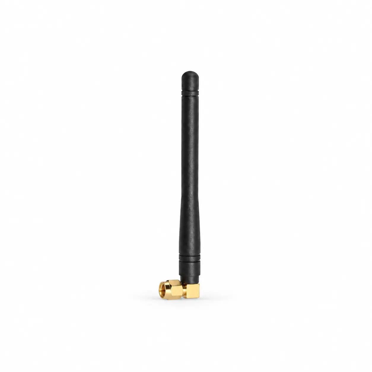
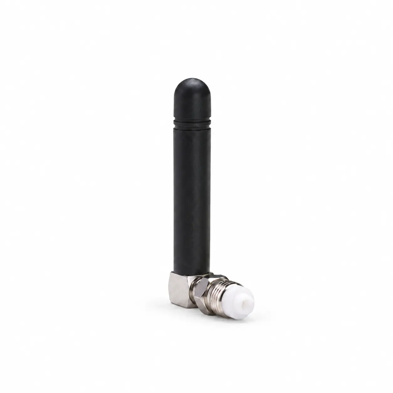
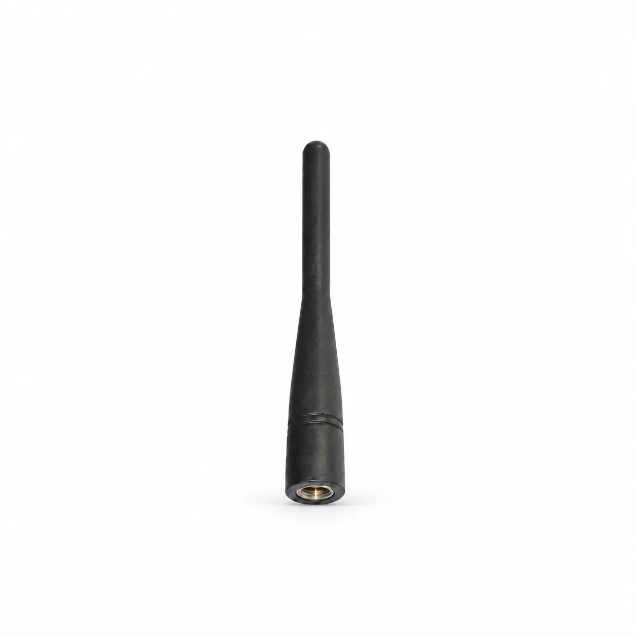
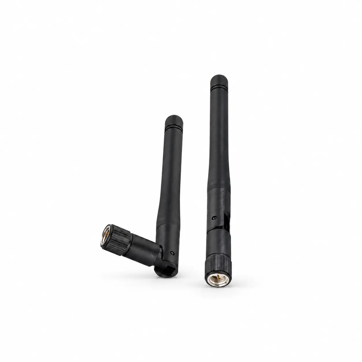
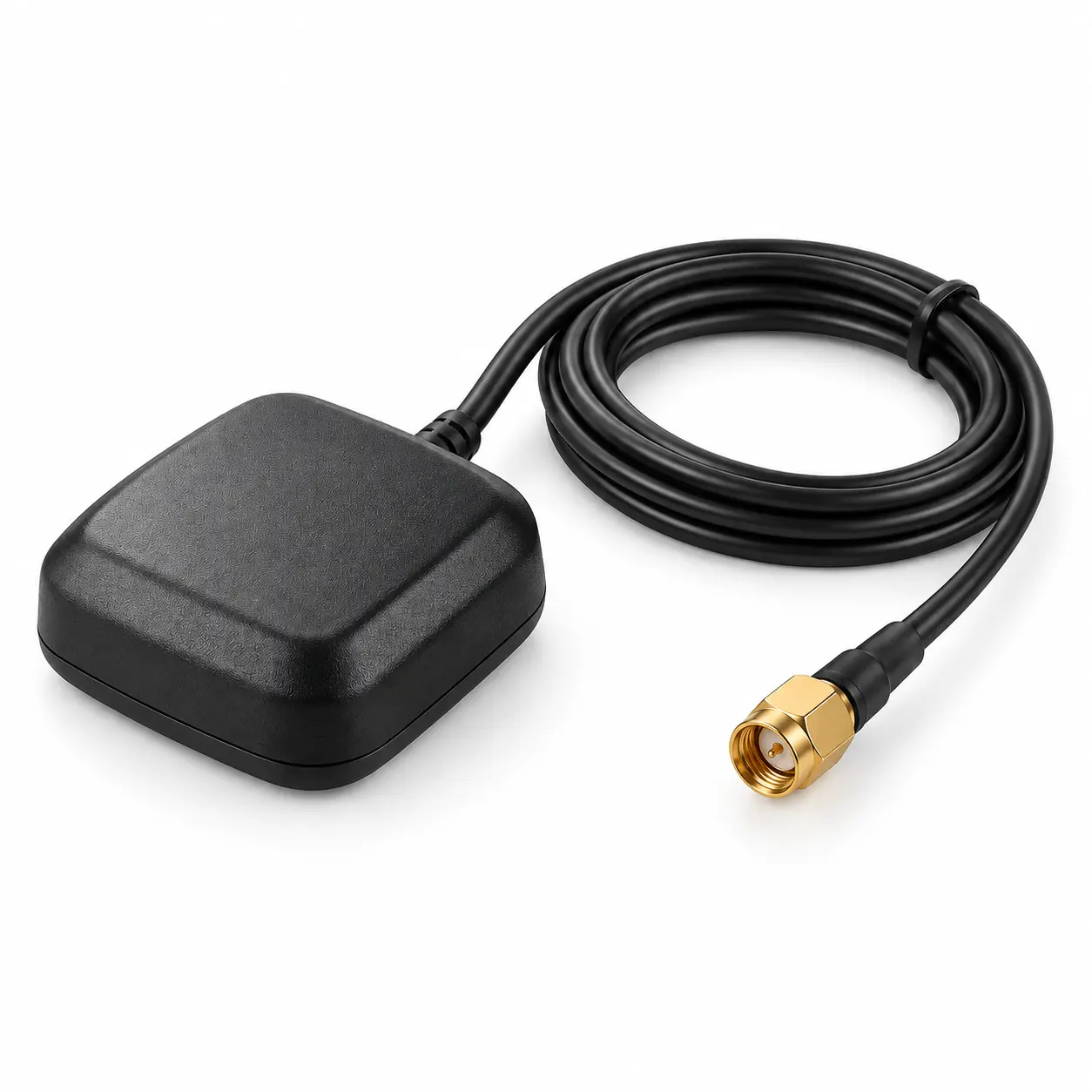
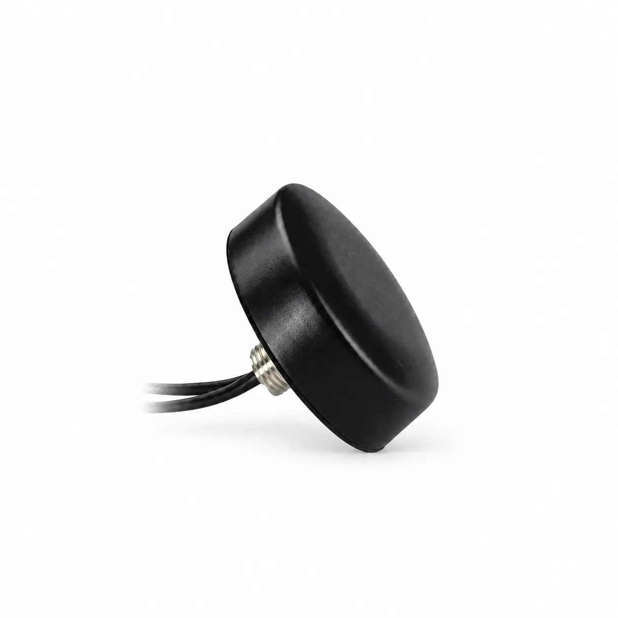
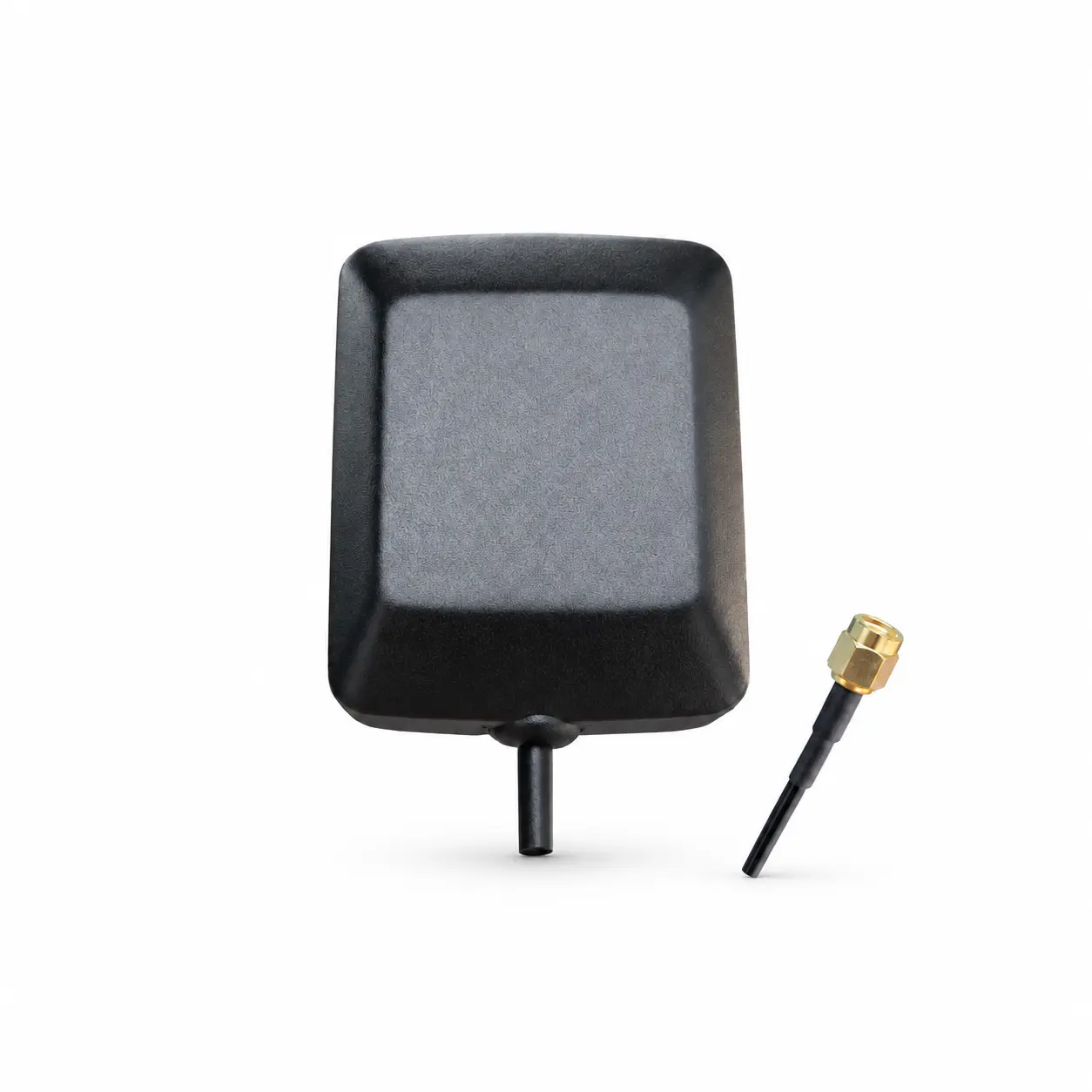
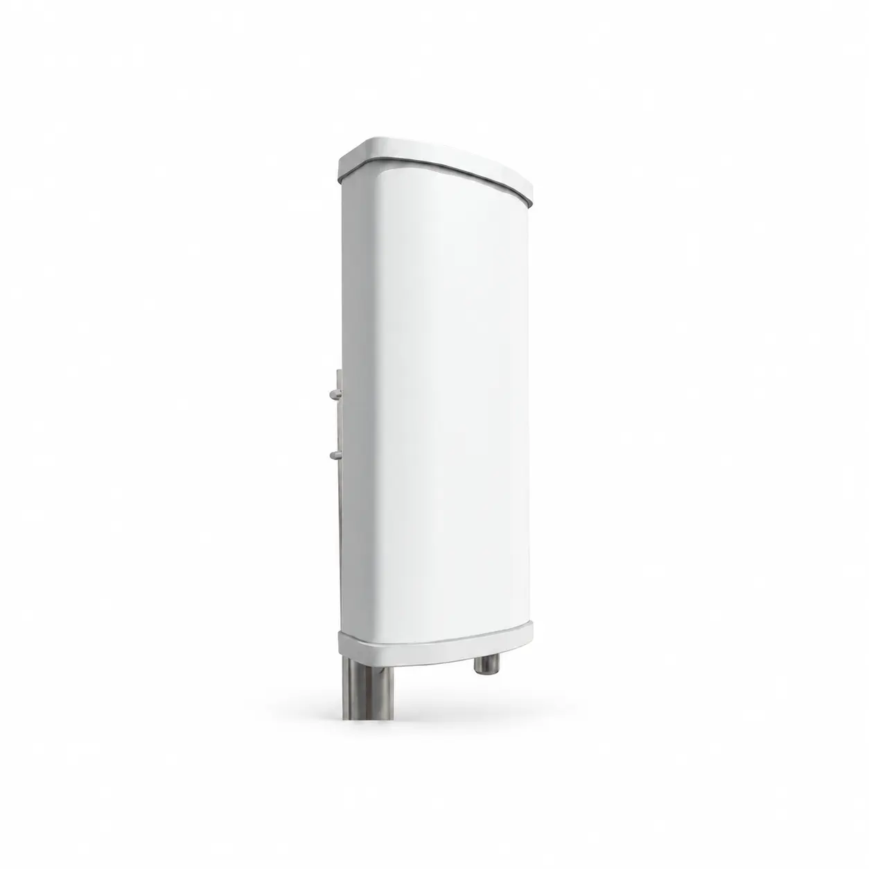
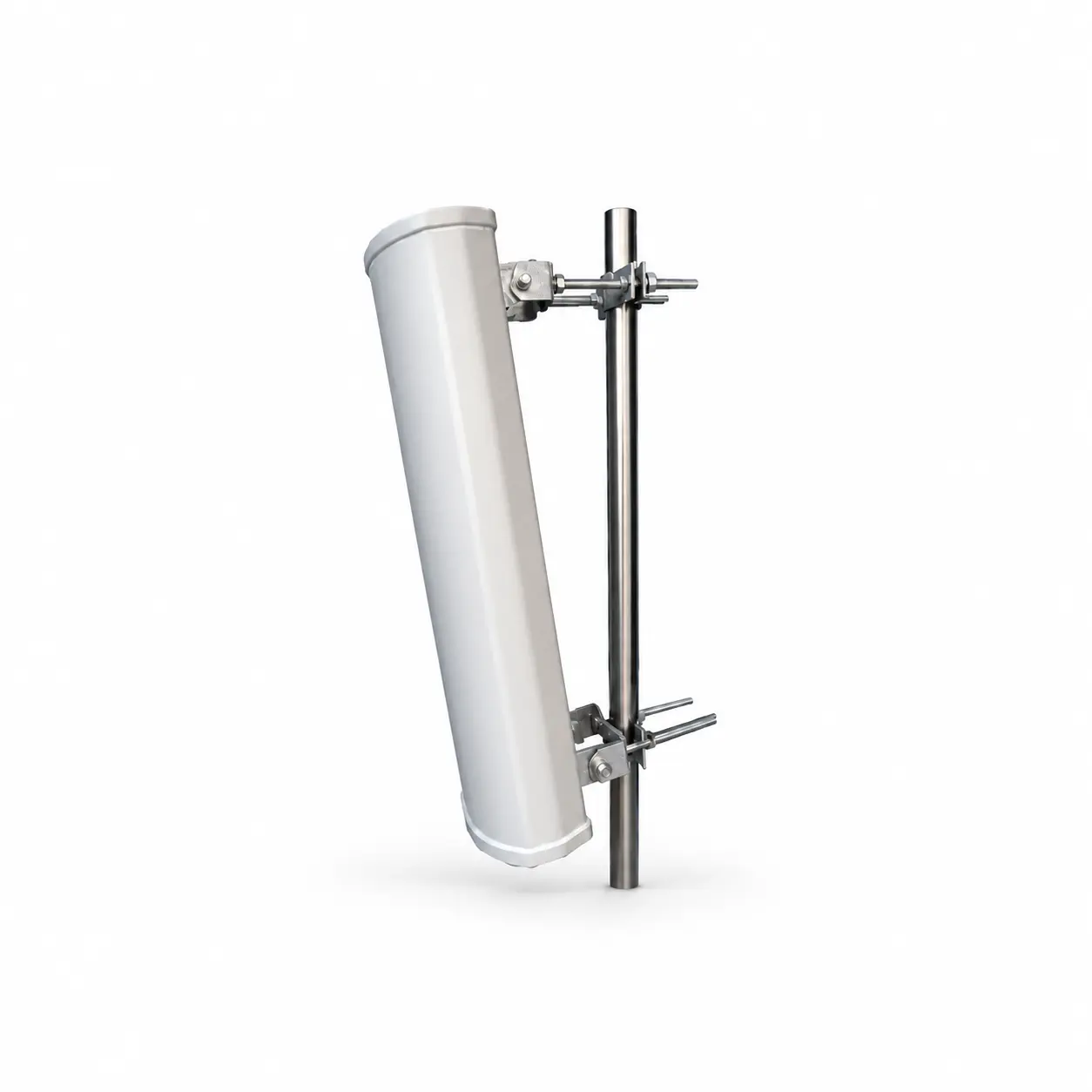
The key selection parameters of antennas can be divided into two major categories: “passive” and “active”.
There are many passive parameters, and here we introduce the commonly used ones.
Bandwidth or frequency band: refers to the operating frequency range that an antenna can meet the system requirements.
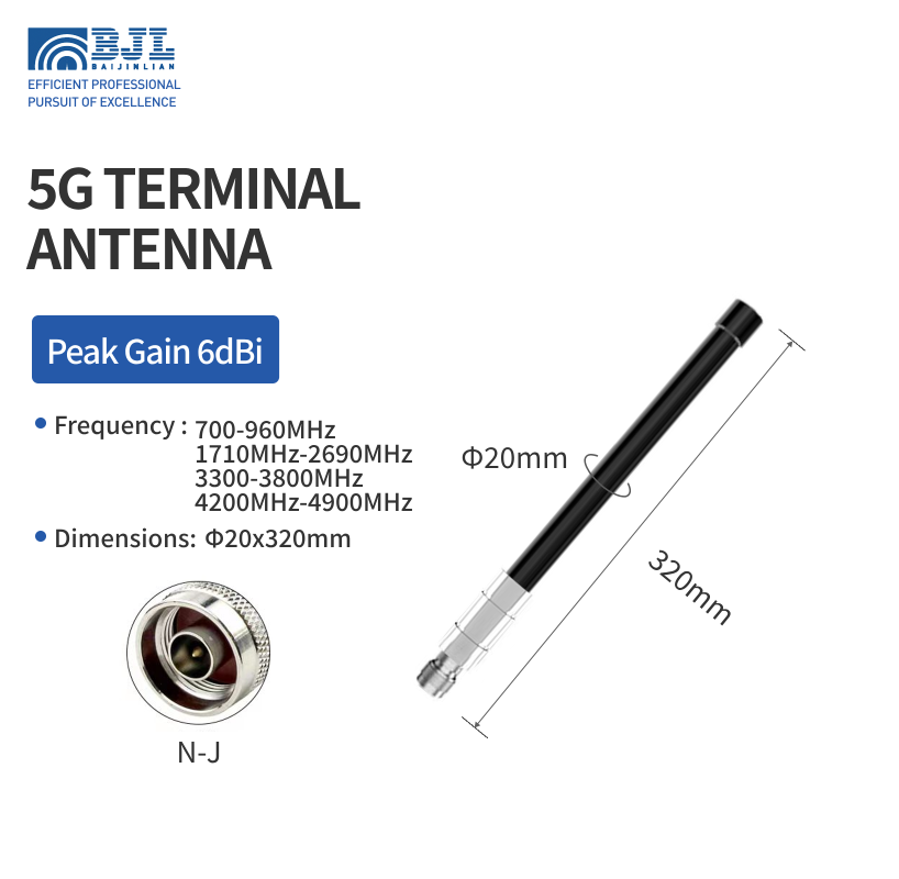
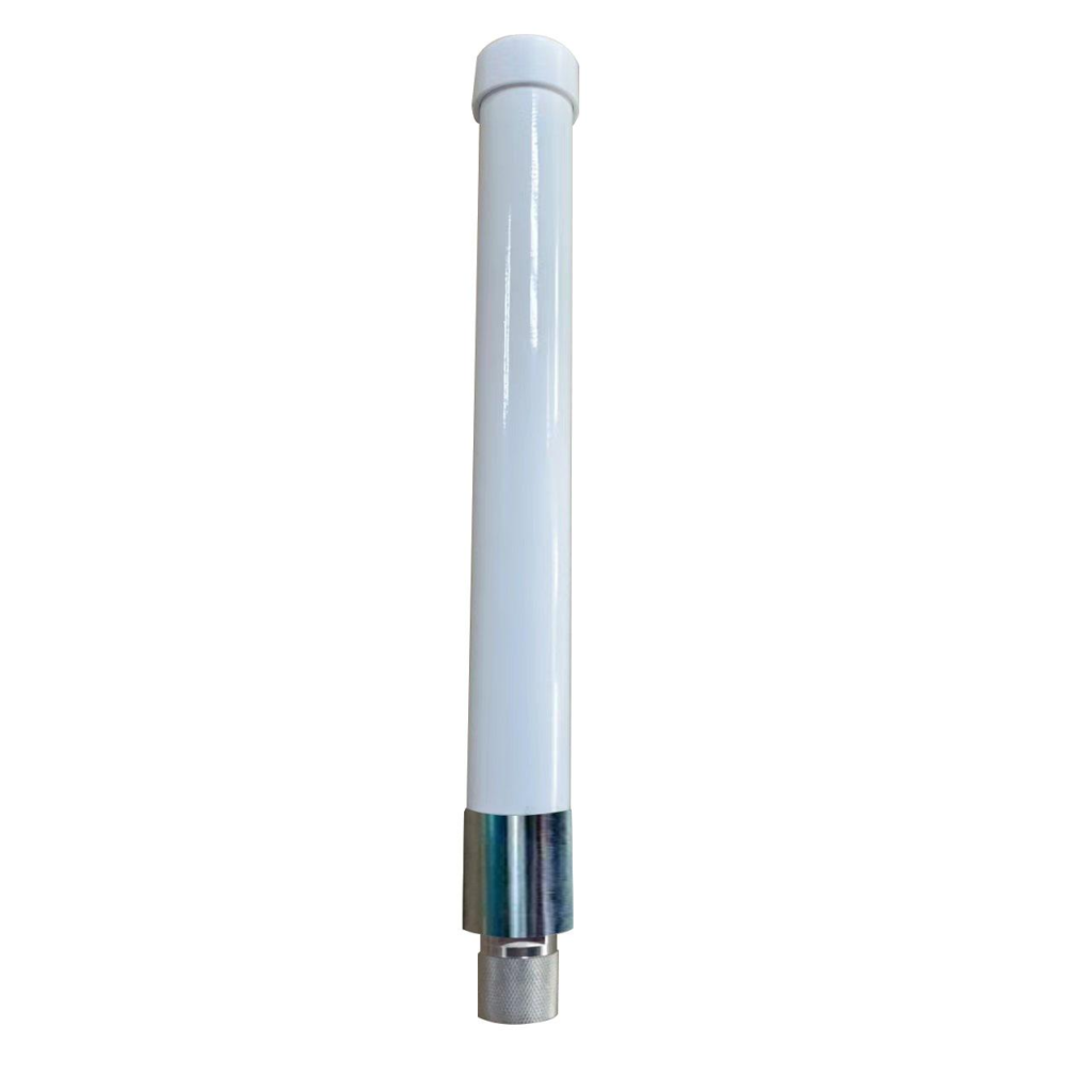
| Model Number | BJL‑B5G06‑T‑NJ20320BL |
| Dimensions | Φ20x320mm |
| Frequency (MHz) | 700‑960MHz,1710MHz‑2690MHz, 3300‑3800MHz,4200MHz‑4900MHz |
| Bandwidth | 260/980/500/700MHz |
| Peak Gain (dBi) | 6dBi |
| VSWR | ≤2.0 |
| Radioactive | Omni‑Direction |
| Polarization Type | Vertical |
| Input maximum power | 100W |
| Impedance | 50Ω |
| Connector | N Male |
| Product material | Fiberglass |
| Operating temperature | ‑40°C to+85°C |
Impedance: Refers to the ratio of voltage to current at the antenna terminals, typically 50Ω, 75Ω, etc. Most consumer electronics antennas are 50Ω. Impedance indicates the matching condition with the transmitter or receiver and affects antenna efficiency.
VSWR (Voltage Standing Wave Ratio): Also known as SWR. Since direct impedance measurement is difficult, VSWR is commonly used. There is a conversion relationship between VSWR and impedance, so VSWR can be used to measure the antenna’s matching condition.
Efficiency: The ratio of the total radiated power to the input power received from the feed line, i.e., η = P_out / P_in. Efficiency measures how effectively the antenna converts high-frequency current into electromagnetic wave energy and is a very important parameter.
Gain: At a given point in a certain direction, under the same input power, the ratio of the square of the field strength produced by the antenna to the square of the field strength produced by an ideal point source antenna at that point. This parameter indicates the antenna’s ability to concentrate energy conversion and efficiency. In layman’s terms, it reflects the antenna’s signal amplification capability and is a very important parameter. The unit of gain is typically dBi. Many online sources incorrectly use DBi, DB, or DBI. Many online gain values for antennas are falsely specified.
Return Loss: Essentially the same as VSWR; it indicates how much signal is reflected back. A more negative value is better, e.g., -20dB is much better than -10dB.
Polarization: The direction of the electric field of the radiated electromagnetic wave. Common types include linear polarization (horizontal/vertical) and circular polarization. Transmitting and receiving polarizations must match; otherwise, the signal will be severely attenuated.
Operating Bandwidth: The frequency range over which the antenna can effectively operate. A wider bandwidth allows covering more frequency bands.
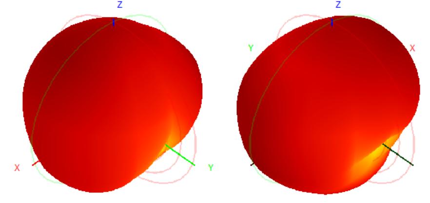
Radiation Pattern: 3D and 2D plots. The 3D plot is created by placing the antenna in a spherical coordinate system and plotting the radiation intensity in all directions. The 2D plot is described by patterns on two orthogonal planes: the E-plane (the plane formed by the electric field vector and the direction of propagation) and the H-plane (the plane formed by the magnetic field vector and the direction of propagation). For some directional antennas used in outdoor products, there are also “beamwidth” and “front-to-back ratio” specifications. “Beamwidth” refers to the angle between the two half-power points on the main lobe (where the field strength drops to 1/√2 of the maximum). For omnidirectional antennas used in outdoor APs or small cells, there are also horizontal and vertical beamwidth parameters. The “front-to-back ratio” is the ratio of the field strength in the direction of maximum radiation to the maximum field strength within the range of 180° ± 60°, usually expressed in decibels.
Active parameters are typically measured in conjunction with relevant protocols and instruments, such as TRP (Total Radiated Power) and TIS (Total Isotropic Sensitivity). Other non-electronic consumer products generally do not require active parameter testing unless there are special requirements.
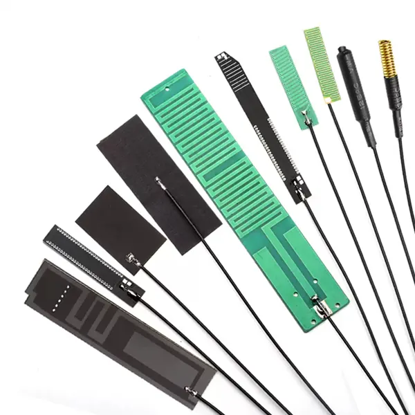
Structural and Morphological Characteristics
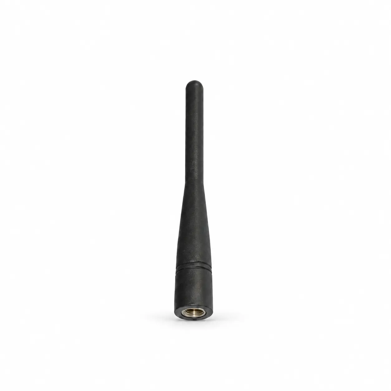
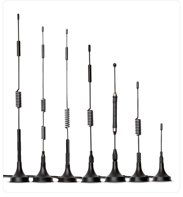
Internal vs. External: Internal antennas (PCB antennas, ceramic patch) are small and low-cost but require a “clearance area” on the PCB. External antennas (whip, suction mount) offer more stable performance and flexible installation.
Physical Size: Antenna length is typically related to the operating wavelength. Antennas for lower frequencies (e.g., 433MHz) are significantly larger than those for higher frequencies (e.g., 5GHz).
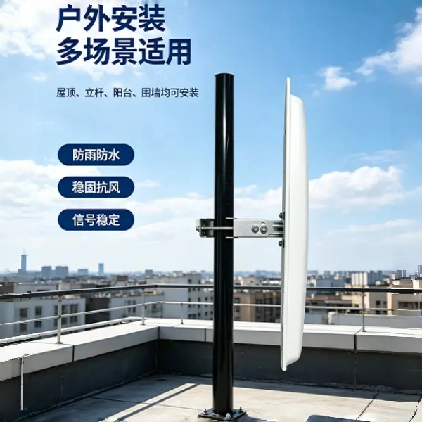
Ingress Protection (IP) Rating: Outdoor antennas require waterproof and dustproof capabilities. A common rating is IP67, with an operating temperature range of -40°C to +85°C.
Scenario Characteristics
Omnidirectional Antenna: 360-degree coverage, suitable for full indoor coverage and multi-device scenarios. Gain is typically between 3-10 dBi.
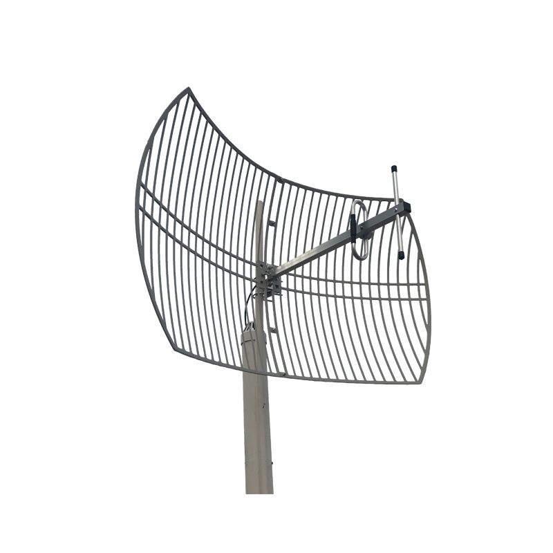
Directional Antenna: Focuses signal in one direction. Gain can reach 15-30 dBi, suitable for long-distance point-to-point transmission, but installation requires precise alignment.
Sector Antenna: Covers a sector area (e.g., 120 degrees), suitable for point-to-multipoint aggregation scenarios